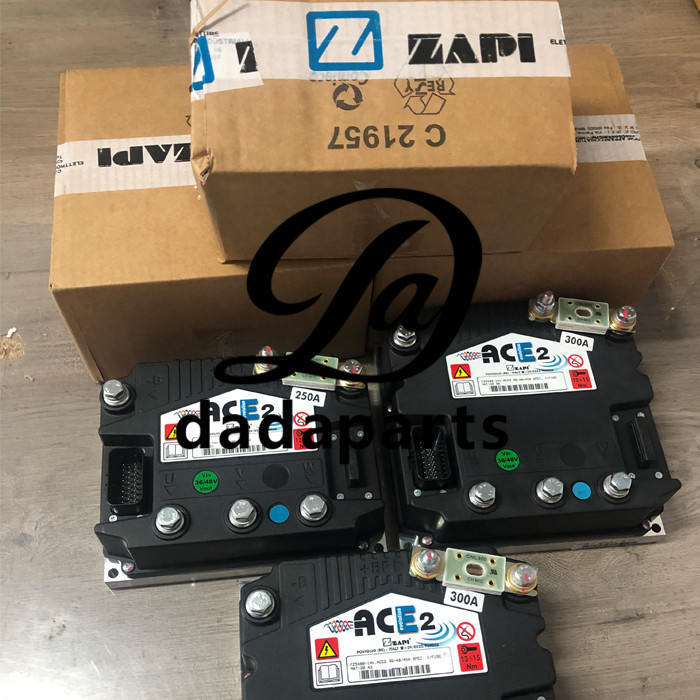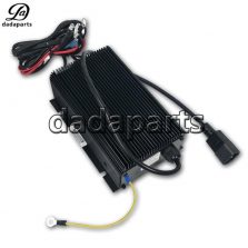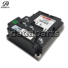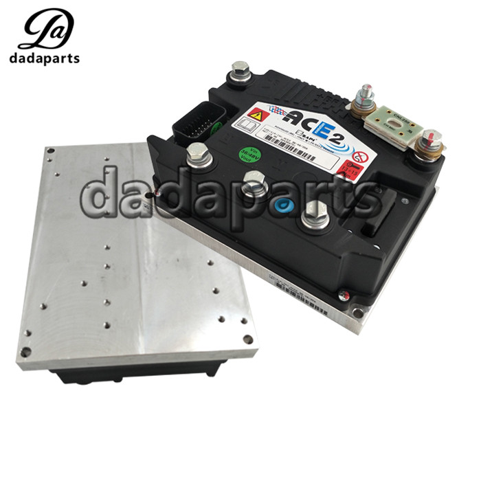
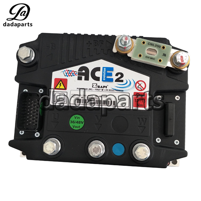
Genuine spare parts zapi ACE2 traction controller 48V350A/400A/450A
| Product name | ZAPI ACE2 Controller |
| DDP# | DDPTMCFTY92E25 |
| Model | ACE2 |
| Voltage | 36V/48V |
| Current | 350A/400A/450A/550A |
| Size | Standard size |
| Color | Black |
| Function | Control vehicle forward and backward ,steering, etc. |
| Used for | Electric forklift CPD15/20 |