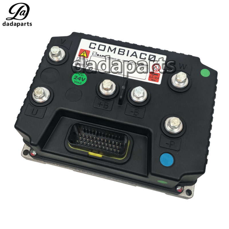
2333-510001-00 traction controller ZAPI AC drive Controller FC2326 COMBIAC0
| Product name | ZAPI AC0 Controller |
| DDP# | DDPTMCFBJZL92E15 |
| Brand | ZAPI |
| PN | 23335100010000 |
| Voltage | 24V/36V/48V |
| Current | 320A/400A |
| Size | Standard size |
| Color | Black |
| Function | Control vehicle forward and backward ,steering, etc. |
| Used for | Electric stacker Electric pallet truck |